Title
Date
Need
Ensure that the motorcycle is clearly visible to other drivers in heavy traffic conditions.
Purpose
Integrate lights into the motorcycle’s rear top case that turn on and off simultaneously with the existing lights.
Requirements
Synchronize existing lights with the new brake and turn signal lights
Design isolated electronics to protect the vehicle’s electronic systems
Use LED lights to reduce power consumption
Applied Solution
Use of addressable RGB LED strip, segmented into three sections: Turn Signal + Position / Brake + Turn Signal
ATtiny85 microcontroller (8-bit, ATMEL) responsible for controlling the lights according to the following logic:
By default, the central section is lit with a dim red.
When the brake is activated, the central section illuminates in bright red.
When the turn signals are activated, either individually or simultaneously, the side sections light up progressively during both turn-on and turn-off.
The progressive blinking frequency of the turn signals is higher than the motorcycle’s original turn signal frequency, allowing the side segments to complete a full blink cycle. This timing is determined by the on/off interval between consecutive LEDs.
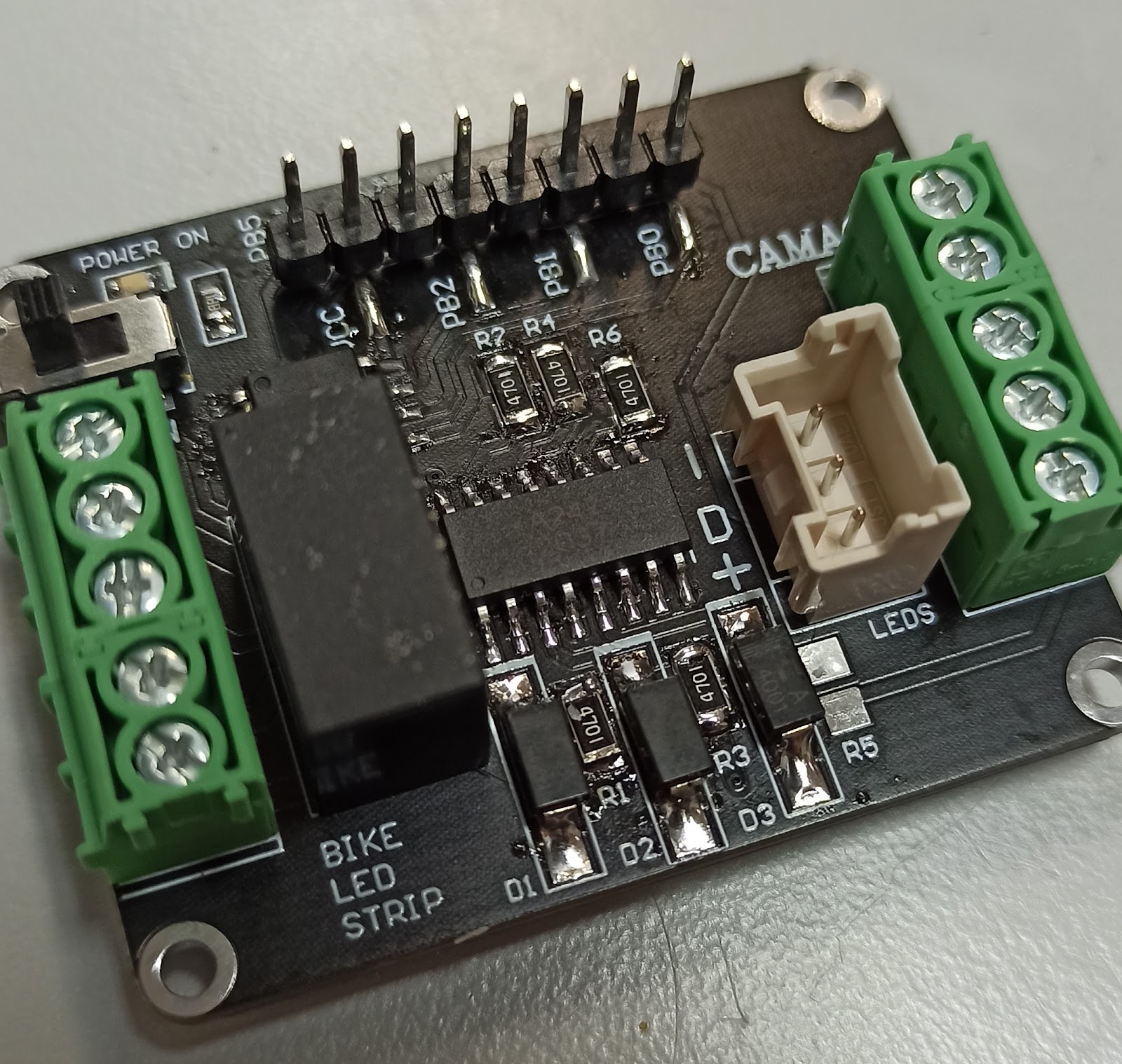
Use of optocouplers to isolate the vehicle electronics from the LED controller. Additionally, they function as a level shifter between the 12V of the existing lights and the 3.3V used by the MCU.
PCB design using Altium Designer, including:
8×1 header for MCU programming
Power switch
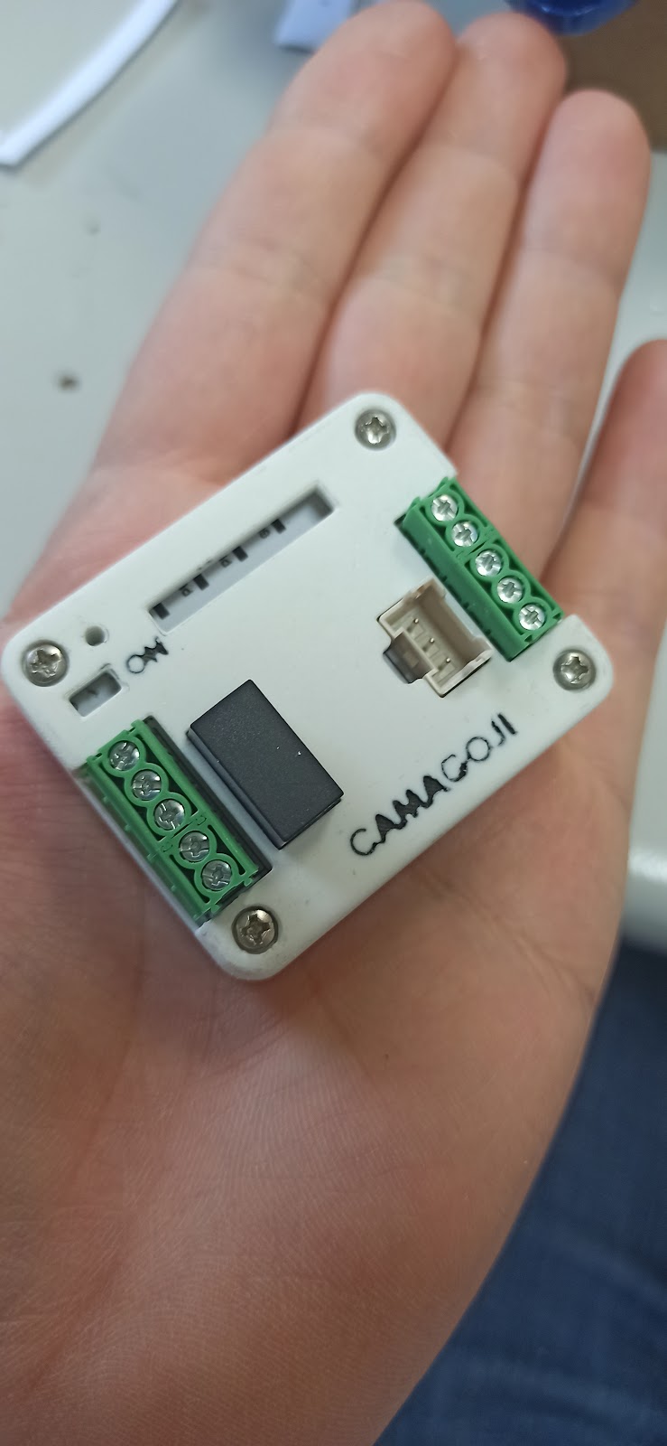
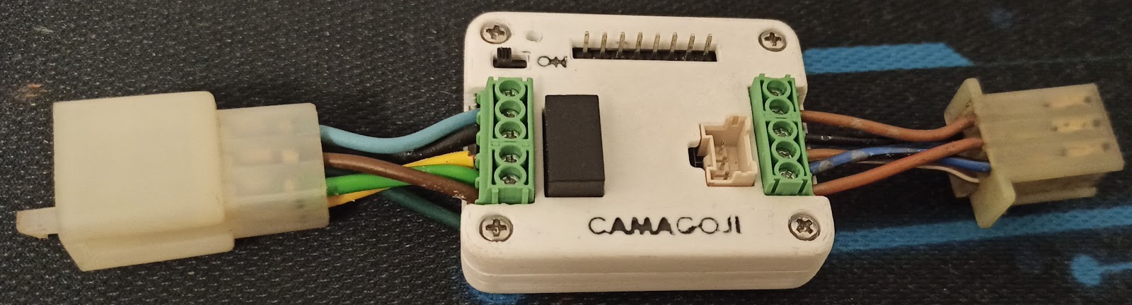
Screw terminals with duplicated pinout on both sides, designed to connect the controller between the existing aerial connector and avoid any modification to the motorcycle’s wiring.
Polarized connector for LED strip
Power supply based on the motorcycle’s fixed 12V
Custom enclosure design in SolidWorks for the PCB.